
Reproject
|
Overview |
|
Overview |
Overview
The Reproject tool enables you to take any file (one which contains geo-coding) and resample it into a new file of a specified map projection. Some key parameters which you can specify are: coordinate reference system (CRS), resolution, interpolation method, and geographic location.
This tool is available both from the GUI and from the command line.
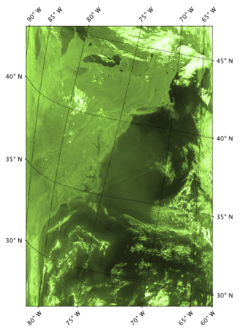
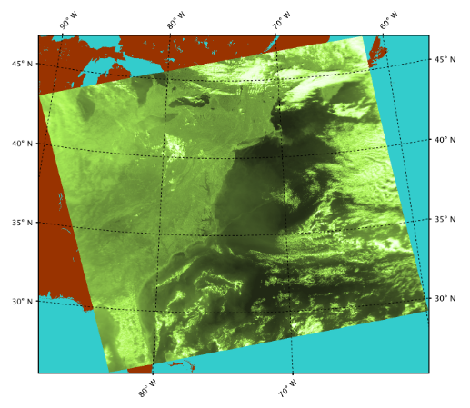
Figures 1a and 1b illustrates the results of applying this tool to a level-2 file using an oblique stereographic projection. The greenish portion of the image is a surface reflectance band and the shape of the level-2 boundary can be seen in the projection. Land (in brown) and water (in aqua) masks have been applied in order to display pixels outside of the original level-2 file boundaries.
Concepts
Valid Pixels and NaNs
There is not a one-to-one correspondance between the pixels of the input file and
those of the output reprojected file. To handle this, the Reproject tool masks out invalid pixels and ultimately
reprojects only the valid pixels of the source file. This hidden automated pixel validation step is acheived using
the following two
criteria: the valid pixel expression and the designation of a no-data value. You can view/modify this
criteria by
right-clicking on any band, and selecting Properties. Alternatively you can view this with the Band
Info tool (Analysis > Band Info)
when selecting the band.
In general this is the desired behavior, unless the valid pixel expression is masking on an ideal range, outside of which there may actually be valid data. If you wish to include this out-of-range data in the reprojection then you will need to edit the valid pixel expression of the band(s) of the source file before reprojecting. One example of this would be when creating true color imagery using surface reflectances. Because the surface reflectance product is designed based on water leaving radiances for the ocean, pixels which image cloud tops can exceed a reflectance value of 1. In this case, for the case of including bright clouds in your true color imagery, the valid pixel expression band(s) of the source file would need to be modified so as to not throw away values above 1.
In general, it may be best to consider mapping a file one way for statistics and another way for displaying data. For statistics you are best served using an equal area map projection (such as Albers Conic Equal Area, Lambert Azimuthal Equal Area, Sinusoidal, ...). With an equal area projection, the Earth surface area is the same for each resultant pixel and can be treated as such with an equal per pixel weighting. However, for large scenes, an equal area map projection may not look natural so using a conformal projection (such as Mercator and Stereographic) is more ideal when displaying this type of imagery.
Note: selection of the "best" map projection is dependent on scene size (is it global, regional, local), scene shape (does it run narrow north-south, narrow west-east, or is it more square in shape), and scene location (is it at the equator, at one of the Poles, or some span of latitudes soemwhere between the Pole and equator.
Upsampling is the process of resampling (remapping) your data to a higher resolution. Upsampling has no inherent problems, other than the fact that the resultant file will be increasingly larger with higher resolutions. A remapped upsampled image will tend to be clearer than one remapped at a resolution comparable with the original input file. The higher the resampling resolution, the closer you approach to seeing the pixel shapes of the original unprojected file.
Note: Ideally a remapped image should not be displayed at a zoom level such that it displays the pixellation of the output file. Such a visual might cause a viewer to incorrectly infer a measurement of noise (or lack of noise) pixel to pixel, when in fact these pixels do not bear a one-to-one correspondance with the native satellite detector measurements.
Downsampling is the process of resampling (remapping) your data to a lower resolution. Downsampling by more than a factor of 4 does have some inherent problems, at least in the SeaDAS Reproject and its related GUI tools (see note 1). This is because SeaDAS currently only offers 3 interpolation methods (nearest neighbor, bilinear, and bicubic) which use a matrix size on the input file of 1x1, 2x2, and 4x4 respectively to generate each remapped pixel of the output file. (See method details.) Downsampling by greater factors than these matrix sizes, will result in many of the pixels in the source file being ignored. Basically, in order to ensure that all source data pixels are being use, if you are downsampling by a factor of 4 then use bicubic, a factor of 2 then use bilinear or bicubic, and a factor of 1 then use any of the three.
Note 1: The resampling(remapping) concept and process is the same in all of the SeaDAS visualization resampling tools: Reproject, Collocate, Mosaic, and Time Series.
Note 2: The SeaDAS OCSSW tools for binning and mapping behave differently and do not ignore any source data pixels for large factor downsampling
Menu Location
The Reproject tool can be accessed in the menu system (Raster -> Reproject) or by clicking the tool bar icon ![]()
This tool is also available from the command line.
Parameters
The following are the set of GUI windows and sub windows which are used to define the reprojection parameters.
This is a tab of the Reproject window
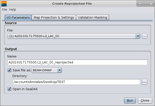
Source
File
This is the file to be reprojected and serves as the input file to the Reproject Tool. You
may
conveniently select one of the files currently loaded in SeaDAS using the drop down selector. In this case, a file
reference number appears to the left of the file name indicating that it is a loaded file and not a direct system
file. To select a file directly from your computer system, use the selector button to the right and navigate to the
desired
file. A file selected this way directly from your system will not have a file reference number displayed next to it.
Note: a loaded file can differ from a system file (even though they may bear the same name) in that you may have made changes to the loaded file in SeaDAS and not saved them.
Output
Name
This is the name of the reprojected file which will be generated. The default behavior appends
"_reprojected" to the original filename.
Save file as
Used to specify whether the file should be physically saved to the file system. The
combo box presents a list of file formats, currently BEAM-DIMAP, GeoTIFF, and HDF5.
Note: if deselected this tool will run much faster as the reprojection does not actually occur at the time of run. Subsequently when the user opens a band in the reprojected file the reprojection occurs for that band only.)
Directory
Location in which to save file. (Default is the last location in which a file was saved)
Note: the default is the last directory saved to by any standard GUI tool in SeaDAS
Open in SeaDAS
Used to specify whether the file should be automatically opened in SeaDAS.
This is a tab of the Reproject window
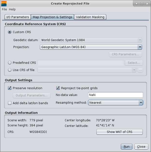
Coordinate Reference System (CRS)
There are 3 options for selecting a CRS: create on yourself - "Custom CRS"; select one - "Predefined CRS"; or use
one
from an existing file - "Use CRS of file".
Custom CRS
With this option you will manually select the map projection (along with it's parameters) and the datum to use.
Geodetic datum
The coordinate system for locating positions on the Earth. In general, these are based on reference ellipsoids used
to represent the shape of the Earth. You can select from a variety of datums. The most common (and SeaDAS default)
is "WGS 84" (WGS 1984, EPSG:4326).
Projection
The map projection (or how the 3 dimensional Earth's surface will be transformed on a 2 dimensional surface).
Select from a list of map projections. If a projection requires parameters then the "CRS Parameters" button will
become selectable.
CRS Parameters
This opens a window of selectable parameters needed by the selected map projection. These contain default values,
but likely
you will want to modify these values based on your scene location or region of interest.
(See CRS Parameters for a more on these
parameters)
Predefined CRS
SeaDAS contains a multitude of pre-defined coordinate reference systems including the EPSG (European Petroleum
Survey Group) Geodetic Parameter
Dataset. Use the selector to the right to choose one
of these projections. (
See Predefined CRS for more on this).
Use CRS of file
Select a file from your system (one with geo-coding) and use the identical map projection criteria and geographic
boundaries of that file. This will have the effect that both files are collocated (same raster grid size and grid
geocoding) but separate files. See the Collocation Tool if you wish to actually merge the files together.
Output Settings
Preserve resolution
Use the SeaDAS defaults which will automatically determine a "best-fit" resolution, output file size, and easting
and westing.
You can deselect this and manually set these parameters.
Add delta lat/lon bands
Specifies whether or not delta latitude and longitude bands will be added to the target product. These are virtual
bands, which can be used to assess the accuracy of the new geo-coding given by the Coordinate Reference System (CRS)
with respect to the old geo-coding.
Reproject tie-point grids
Specifies whether or not the tie-point grids shall be included. If they are reprojected they will appear as bands in
the target product and not any more as tie-point grids.
No-data value
The default no-data value is used for output pixels in the projected band which have either no corresponding pixel
in the source product or the source pixel is invalid.
Resampling method
This is the interpolation method. Choose between Nearest, Bilinear, and Bicubic. (See details)
Scene width
This will be the width in pixels of the output file.
Scene height
This will be the height in pixels of the output file.
Center longitude
This is the longitude of the center of the source file.
Center latitude
This is the latitude of the center of the source file.
CRS
This is name of the chosen projection and datum
Show CRS WKT
This is the CRS WKT (well-known text)
This is a sub window of options launched from the Map Projection & Settings window
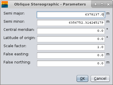
Semi-Major
The semi-major axis of the planet's shape treated as an ellipsoid, which in the case of the Earth, is the equatorial
radius.
This value is automatically filled based on the datum (reference ellipsoid) which you selected.
Semi-Minor
The semi-minor axis of the planet's shape treated as an ellipsoid, which in the case of the Earth, is the polar
radius.
This value is automatically filled based on the datum (reference ellipsoid) which you selected.
False Easting
This is the distance away from the origin (x component) to place the reference pixel. This essentially has the
effect of
shifting the geographic boundaries of your output file sideways. (More details)
False Northing
This is the distance away from the origin (y component) to place the reference pixel. This essentially has the
effect of
shifting the geographic boundaries of your output file up and down. (More details)
Map Projection dependent fields
Each map projection may have additional fields dependent on the particular projection. Some of these parameters are:
Latitude of center
Longitude of center
Central meridian
Latitude of origin
Scale factor
Azimuth
Standard parallel 1
...
This is a sub window of options launched from the Map Projection & Settings window
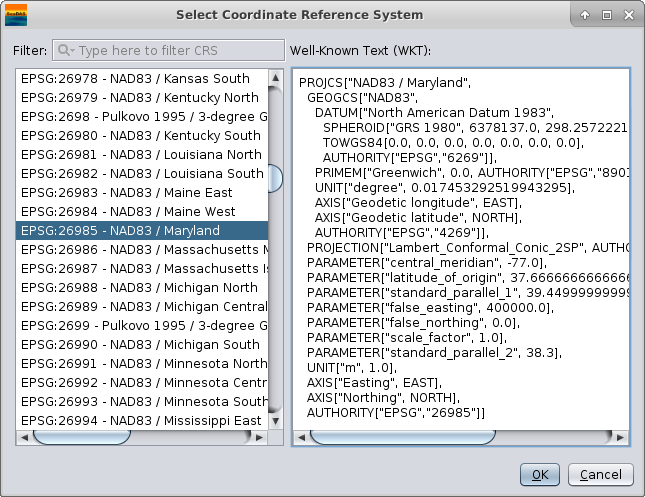
Select a CRS in the left window of this GUI and an XML text representation of the selected projection will be displayed and loaded in the right side of this GUI . If you look at the XML, you can see all the individual parameters which go into the particular projection. You could replicate or deviate from these parameters if you wish by instead using the "Custom CRS" option of the parent window and manually setting these parameters.
Note 1: as of SeaDAS 7.5, the EPSG dataset being used is version 7.9.0
Note 2: you can use this XML or the authority code when running Reproject in the command line mode.
This is a sub window of options launched from the Map Projection & Settings window.
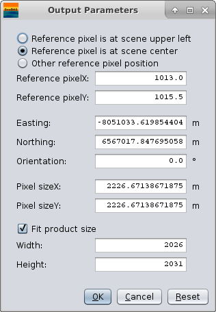
Reference Pixel
This is the pixel of your output file to use for setting the easting and northing.
Reference pixel is at scene upper left
In this case the upper left pixel of the output file will be used as the reference.
Reference pixel is at scene center
In this case the center pixel of the output file will be used as the reference.
Other reference pixel position
In this case you custom specify which pixel of the output file will be used as the reference.
Easting
This is the distance away from the origin (x component) to place the reference pixel. This essentially has the
effect of
shifting the geographic boundaries of your output file sideways. (More details)
Northing
This is the distance away from the origin (y component) to place the reference pixel. This essentially has the
effect of
shifting the geographic boundaries of your output file up and down. (More details)
Orientation
This is the angular rotation of the output image. It is the angle between geographic north and map grid north (in degrees),
in other words, the convergence angle of the projection's vertical axis from true north.
Pixel sizeX
This is the resolution in the x direction of the output image. The units are dependent on which CRS you have
defined.
Pixel sizeY
This is the resolution in the y direction of the output image. The units are dependent on which CRS you have
defined.
Fit product size
This is used to define the width and height in pixels of the output file such that all data from the input file
will be "best fit" and fully included in the output file.
Of note and caution is that SeaDAS (as of version 7.5) uses the width and height setting and ignores this checkbox
when Reproject runs.
Really the wording on this should be "Edit sizing". We will have to look into this. Regardless, clicking "Reset"
will set
these values for the width and height to "best fit".
Width
This is the desired width in pixels of the output file.
Height
This is the desired height in pixels of the output file.
A bit more about the Easting and Northing fields and the Reset button
The Easting and Northing fields can be a bit intimidating and not so intuitive, however basically you need to ask
yourself whether
you want the geographic boundaries of your output file to be adapted to "best-fit" and include all the data from the
input scene, or
whether you have a specific and exact geographic boundary for your output file in mind.
For the former "best fit" case, SeaDAS can calculate default Easting and Northing values based on your scene boundaries and CRS criteria. To do this, click the "Reset" button at the bottom of this GUI window. Of note is that the very first time you open this sub window during a SeaDAS session, the default will be calculated and applied, but from that point onward the assumption is that the value in the textfield is the value which you want to use If you make further changes to the CRS criteria or change to a different file, then you will again need to click "Reset".
For the latter case, since the false easting and false northing fields also appear with the CRS definition it may be better or perhaps more clear to set them there and then set the values here to 0.0 for each. Either way, keep in mind that the actual false easting and false northing is the sum of the corresponding values in the CRS parameters and Output Parameters.
Note: Easting, northing and the pixel size are given in the units of the underlying map (e.g. dec. degree for geographic and meter for the UTM projection).
This is a tab of the Reproject window.
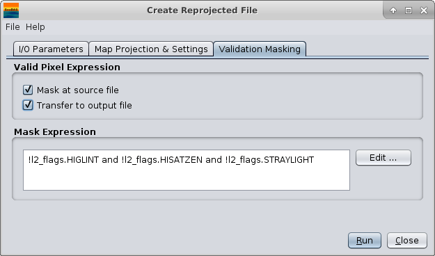
Valid Pixel Expression
Each band of the source file has a valid pixel expression which designates whether a pixel is valid for display
or some other operation. These expressions are unique to each band. When reprojecting a source file you want to
consider whether or not to allow the "invalid" pixels to be used or ignored. The default behavior is to treat
these pixels as "invalid". However, the following two parameters govern how the valid pixel expression of the source
bands will be treated during reprojection.
Mask at source file
When this is selected the pixels which are not "valid" will be ignored. When this is deselected, the pixels which
are not "valid" will be used in the reprojection process.
Transfer to output file
When this is selected the logical expression itself will be copied from each source band to its corresponding
band in the reprojected file. If deselected, then the valid pixel expression of the reprojected band will be empty.
Mask Expression
In addition to the option of masking out invalid pixels as designated by the valid pixel expressions of the source
bands, you can create a custom logical expression to further constrain which pixels of the source band get used.
Edit ...
This accesses the Expression Editor to help you construct a logical expression. Note that the mask expression
you create here is applied to each of the bands.
Metadata
The following meta data is added to the output file by this tool. All the rest of the original meta data from the
input file is retained and included in the output file
| Name | Description |
|---|---|
Reproject_gpt_parameters |
The full GPT operator parameter xml string used in the creation the output file |
crs |
The coordinate reference system (WKT) used in the creation of the output file |
map_projection |
The map projection name used in the creation of the output file |
history |
"Reproject" is prepended to original history value |
spatial_resolution |
If exists in original file, "Derived from" is prepended to original value |
processing_level |
If exists in original file, "Derived from" is prepended to original value |
product_name |
If exists in original file, "Derived from" is prepended to original value |
title |
If exists in original file, "Derived from" is prepended to original value |
Command Line Tool (GPT)
The Reproject tool can also be run from the command line using SeaDAS GPT (graph processing tool). All parameter options within the GUI are also supported for the command line version with a few minor parameter name differences which will be noted below.
GPT "collocatedWith" = GUI "use CRS of file"
GPT "crs" can be either XML or the EPSG Authority (for example EPSG:4326, AUTO:42001, etc.)
GPT "wktFile" as an input is not available in the GUI, but the GUI can create and display the CRS WKT of the
specified CRS
parameters
which could subsequently be used on the command line.
Note: The GPT Reproject tool also includes the Orthorectification.
Revision History