
| MERIS Level 1 Radiometric Processor - MERIS Smile Correction Algorithm Specification |
|
MERIS is measuring the reflected sun light using CCD technique. A CCD is measuring in one of its dimensions one image line, and in the other dimension the spectral dispersed radiance for each pixel along the image line. I.e., the spectral measurement of each pixel along an image line is made by its own set of sensors of the CCD. This causes small variations of the spectral wavelength of each pixel along the image. This is called the "smile effect".
The MERIS instrument is composed of 5 cameras, each equipped with its own CCD sensor. The variation of the wavelength per pixel are in order of 1nm from one camera to another, while they are in the order of 0.1nm within one camera.
Even though this variation is small compared to the spectral bandwidth of a band, which is typically 10nm, and can hardly be seen in an image, it can cause disturbances in processing algorithms which require very precise measurements, for example the retrieval of chlorophyll in the ocean. These disturbances can result in visual artifact ("camera borders") or reduced accuracy of the Level 2 products.
Therefore, the MERIS Level 2 processor corrects the smile effect. The Level 1b product is not smile corrected, because this product shall provide the user exactly what the instrument is measuring, and that is in fact the radiance at the given wavelength of each pixel.
The Smile Correction is an exact implementation of the Level 2 smile correction, so that the users have a tool to generate smile corrected Level 1b products. While the Level 1b product provides the radiance measurement for individual wavelengths within one spectral band, the smile corrected product has normalised the wavelengths within one spectral band to one reference wavelength. Table 1 provides the reference wavelengths and the reference solar irradiance for this band. Please note that the reference solar irradiance is not corrected for the daily variation.
The smile correction consists of two terms: the irradiance correction and the reflectance correction.
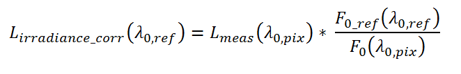
The irradiance correction corrects the variation of the solar irradiance, which is different between the wavelength of the pixel and the reference wavelength:
Equation 1:
The reflectance correction is interpolating along the slope of the reflectances between adjacent wavelengths from the pixel-wavelengths to the reference wavelength:
Equation 2:

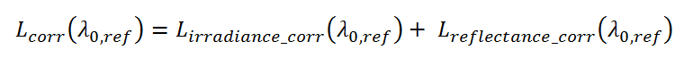
The smile corrected radiance is the sum of the two terms:
Equation 3:
While the irradiance correction can be applied to all 15 bands, it is not possible to define for each band two adjacent bands, which are suitable universally to give a good estimation of the spectral slope within the band. In order to overcome this problem at least partially, different adjacent bands have been selected for land and water pixels. However, for the bands in absorption lines, i.e. bands 11 and 15, it is totally impossible to find suitable adjacent bands. Table 1 specifies the bands, which are reflectance corrected, and which bands are being used as adjacent bands. These settings are specified in an auxiliary table and can be changed there.
|
Land
|
Water
|
|||||||
|
band (lam_0) |
activation switch |
lower band (lam_1) |
upper band (lam_2) |
activation switch |
lower band (lam_1) |
upper band (lam_2) |
reference wavelength (lam_ref) | F0_ref |
| 1 | 1 | 1 | 2 | 1 | 1 | 2 | 412.5 | 1713.69 |
| 2 | 1 | 1 | 3 | 1 | 1 | 3 | 442.5 | 1877.57 |
| 3 | 1 | 2 | 4 | 1 | 2 | 4 | 490 | 1929.26 |
| 4 | 1 | 3 | 5 | 1 | 3 | 5 | 510 | 1926.89 |
| 5 | 1 | 4 | 6 | 1 | 4 | 6 | 560 | 1800.46 |
| 6 | 1 | 5 | 7 | 1 | 5 | 7 | 620 | 1649.70 |
| 7 | 1 | 6 | 9 | 1 | 6 | 9 | 665 | 1530.93 |
| 8 | 1 | 7 | 8 | 0 | 7 | 9 | 681.25 | 1470.23 |
| 9 | 1 | 9 | 10 | 1 | 8 | 9 | 708.75 | 1405.47 |
| 10 | 1 | 10 | 12 | 1 | 10 | 12 | 753.75 | 1266.20 |
| 11 | 0 | 10 | 12 | 0 | 10 | 12 | 761.875 | 1249.80 |
| 12 | 1 | 10 | 12 | 1 | 10 | 12 | 778.75 | 1175.74 |
| 13 | 1 | 13 | 14 | 1 | 13 | 14 | 865 | 958.763 |
| 14 | 1 | 13 | 14 | 0 | 13 | 14 | 885 | 929.786 |
| 15 | 0 | 13 | 14 | 0 | 13 | 14 | 900 | 895.460 |
Table 1: Standard configuration of the smile correction (equal to the current setting in the Level 2 processor). The activation switch defines if the reflectance correction is applied or not. The lower and upper band indices specify the adjacent bands which are used in the reflectance correction. The reference wavelength is the wavelength to which all pixels of a band are normalised, and the F0_ref column lists the solar irradiance (not day-corrected) which are used for the irradiance correction. These solar irradiance are irradiances which are integrated over the spectral widths of the band.