
| Level 3 Binning Operator |
|
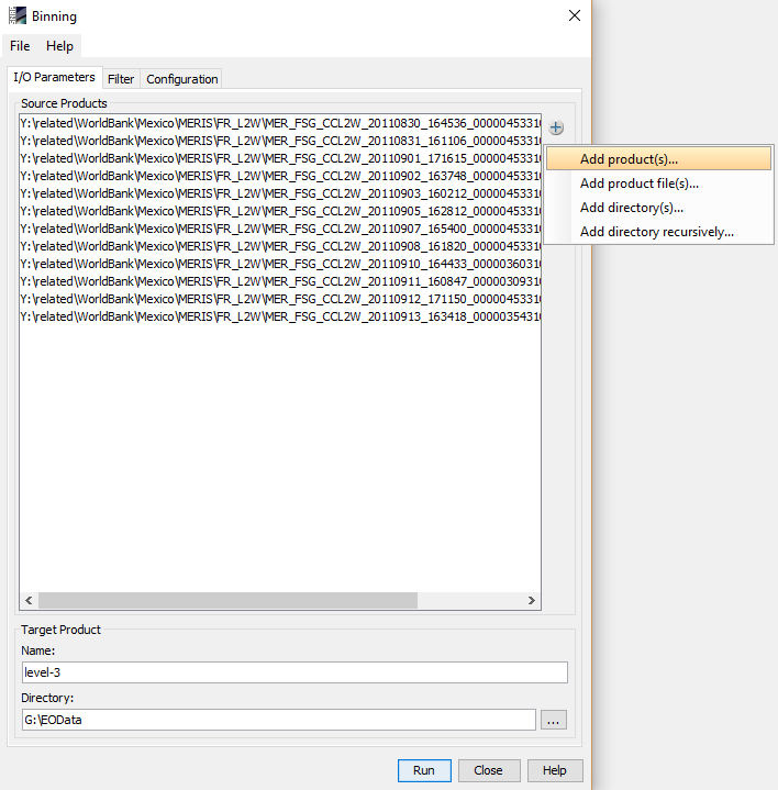
Using the I/O Parameters tab, the input products can be set, as well as the target product's name and target directory. See the screenshot below.
Two filters can be applied to limit the contents of the target product. See the screenshot below for the user interface for the filters.
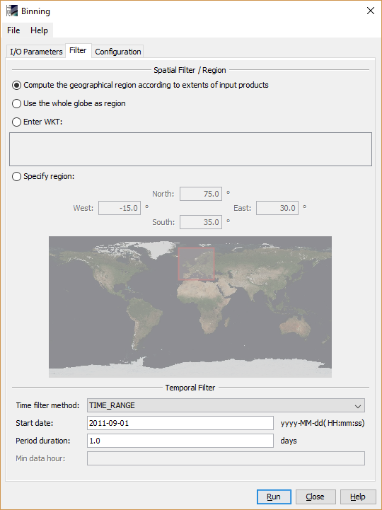
The target region filter can be used to set the bounds of the target product. It is able to operate in four different modes:
The method that is used to decide which source pixels are used with respect to their observation time.
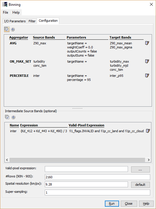
In the upper table the user can specify which data should be aggregated.
Using the plus button
aggregation definition can be added. Depending on the selected aggregation method
(AVG, MIN_MAX, ON_MAX_SET, PERCENTIL, ...) different
parameters can be specified. Multiple aggregation definition can be added.
The edit button on the right hand side can be used to change to configuration of an existing aggregation definition.
The Intermediate Source Bands table has 3 columns: "Name", "Expression" and "Valid-Pixel Expression".
It allows the user to define intermediate bands which are actually not part of the source products. These bands are defined by arithmetic band
expressions. After defined here, they are selectable as source band for the aggregators.
The 3rd column is optional and allows to specify a valid pixel expression. If not given, it will be generated by
combining the valid pixel expression of all bands referenced in the expression. Setting it to true makes all pixels valid.
Using the valid expression, the user can specify which values in the source products shall be considered. Thus, a
boolean expression has to be set here. In the configuration of the example screenshot, only pixels that are not over
land are considered.
The target height of the source product may be set, too; this value has direct influence on the spatial resolution.
As long as the area of an input pixel is small compared to the area of a bin, a simple binning is sufficient. In this case, the geodetic center coordinate of the Level 2 pixel is used to find the bin in the Level 3 grid whose area is intersected by this point. If the area of the contributing pixel is equal or even larger than the bin area, this simple binning will produce composites with insufficient accuracy and visual artifacts such as Moiré effects will dominate the resulting datasets.
The following figure illustrates this problem.
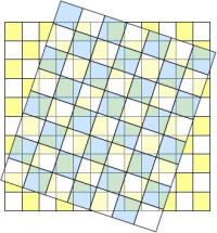
Level 2 grid (blue) and Level 3 grid (yellow)
The blue chessboard grid refers to the input data, the yellow one refers to the final Level 3 grid. As the figure clearly shows, single Level 2 pixels cannot be uniquely be assigned to single bins.
Supersampling parameter can be used to reduce or avoid the Moiré effect. The Moiré effect usually occurs when the spatial resolution used for the binning is similar to or smaller than the input pixel resolution. The supersampling subdivides every input pixel to n x n subpixels which all have the same values but different and unique geographical coordinates. This way, an input pixel may be distributed to more than one adjacent bin cell.